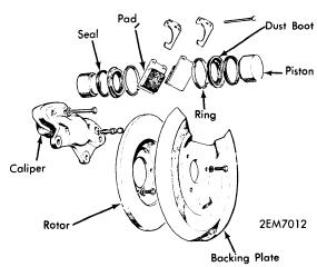
DESCRIPTION
Cricket disc brakes are hydraulically operated. Brake assembly consists of a rotating disc attached to hub, caliper mounted to stub of axle carrier, a disc, a cylinder on each of caliper housing, a piston, a pair of brake pads between disc and pistons retained by pins and spring clips. Rear brake drum incorporates a primary and secondary brake shoe. Rear brakes are operated by a double-acting wheel cylinder. A separate handbrake automatically adjust rear brake lining. Master cylinder and power brake unit supply needed hydraulic pressure to operated brake system. A brake warning light is activated if either system loses hydraulic pressure.
ADJUSTMENT
Disc Brakes - No adjustment required.
Drum Brakes - No adjustment required.
Handbrake - Only required adjustment when cable becomes stretched. On sedan models only, remove cable yoke from lever. Set both adjusters in released position and rotate sleeve of adjuster. Yoke must fit freely into lever.On station wagon models only, disconnect left-hand cable at yoke. vertically position bellcrank on right-hand brake rod and center hole in operating lever 3/4" to rear of a line parallel to axle. With bellcrank in position and without pulling on left cable, position yoke on left-hand lever.
BLEEDING SYSTEM
Bleed rear brakes first beginning with left side. With pressure on pedal, open bleed fitting and push pedal its full travel. When pedal is fully depressed, close fitting and let pedal return to fully released position. Move forward and repeat procedure starting on right side.
REMOVAL & INSTALLATION
POWER BRAKE UNIT
Check Valve Replacement - Press down on valve and turn on-third turn counterclockwise. Remove valve by pulling and applying side pressure. Install new "O" ring. Lubricate new grommet, place in front shell and push in new check valve. Press hard to seat "O" ring and turn one-third turn clockwise engage retaining tongs.
Filter Replacement - Disconnect operating rod from brake. Remove four nuts from mounting studs. Detach four-way connector from inner fender shield. Pull whole unit forward enough to reach filter. NOTE - Do not lose spacers. Remove filter diaphragm plate and press new filter into neck of diaphragm
Removal - Withdraw retaining pin and clips. Lift out pads and clamping clips.
Installation - Install new pads by opening bleed screw, pushing piston to bottom of bore and closing bleed screw. Secure new pads with new retaining clips and pins. Pump pedal to reposition pads.
LINING REPLACEMENT (DRUM BRAKES)
Removal - Remove countersunk screw and lift off brake drum. Remove hold-down springs and clips. Pry shoe away from backing plate and lift off shoes.
Installation - Transfer lever stop clip to new shoe. Screw adjuster to forked end of push rod. Position rear shoe in wheel cylinder and handbrake assembly. Insert push rod into female adapter and position primary shoe in forked end of push rod and wheel cylinder. Install springs, clips and pins. Screw adjuster into operating position.
BRAKE ROTOR (DISC)
Removal - Remove brake caliper complete with pads. Remove dustcap, cotter pin, plain nut and washer. Lift-off complete hub assembly.
Installation - Install hub assembly complete with inner bearing and grease seal. Insert outer bearing, plain nut and washer. Adjust wheel bearing to specifications. Install cotter pin and dust cap. Fit caliper and pads to rotor.
 |
| FRONT BRAKE ASSEMBLY |
BRAKE CALIPER
Removal - Drain brake fluid through bleed screw and remove metal brake line. Remove two mounting bolts and lift off whole caliper assembly. NOTE - Do not split caliper in two.
Installation - Reverse removal procedure.
MASTER CYLINDER
Removal - Disconnect brake lines, detach push rod from foot pedal (models without power brakes) and remove mounting bolts to lift off cylinder.
 |
| TANDEM MASTER CYLINDER |
Installation - Reverse removal procedure.
POWER BRAKE UNIT.
Removal - Disconnect operating rod from brake pedal. Disconnect brake lines and vacuum hose. Remove mounting nuts and washers. Lift off power brake unit and master cylinder as a unit.
Installation - Reverse removal procedure. NOTE - Ensure spacers are replaced in original position.
OVERHAUL
BRAKE CALIPER
Disassembly - Remove brake caliper and pads. Place a clean rag between pistons and blow compressed air into inlet connection forcing piston from cylinder. Using a suitable tool (probe or equivalent) pull piston from bore. NOTE - Avoid damage to annular groove.
Cleaning & Inspecting - Clean all parts in approved grade brake fluid or alcohol. Inspect both bores and pistons for grooves or score marks.
Reassembly - Lubricate cylinders with brake fluid and position sealing rings in grooves. Insert piston fully into cylinder and replace dust boot, retaining ring and brake pads. Install caliper. NOTE - Ensure all shims have been installed. Reconnect brake line and bleed system.
MASTER CYLINDER
Disassembly - Remove reservoir and compensating valve. Separate piston and intermediate spring. Lift leaf of spring, retainer and remove spring and center valve sup-assembly. Remove spring, valve spacer, and spring washer from valve head and stem. Remove seals from secondary pistons and pry out baffle.
Cleaning & Inspection - Clean all parts in approved grade brake fluid or alcohol. Examine both bore and pistons for pits or score marks.
Reassembly - Lubricate all parts before installation . Position valve seals in valve head, position spring washer so flare is away from stem shoulder; install valve spacer legs first. Attaching spring retainer to valve stem, keyhole first. Slide secondary spring over spring retainer, position sub-assembly on secondary piston. NOTE - Spring must be compressed while leaf of spring retainer is pressed behind head of piston. Fit intermediate spring into position. Insert piston assembly into bore, valve end first. Press primary piston down to fit, compensating valve assembly. Fit seal, screw in compensating valve and tighten. Install reservoir and refill.

