1972-74 Chevrolet LUV
DESCRIPTION
Axle housing is banjo type with removable differential carrier and semi-floating axle shafts. Ring and pinion gears are hypoid type in which centerline of pinion is set below centerline of ring gear. Differential case is one piece, two pinion design. The axle shafts are retained in housing by cone type roller bearing retainers at axle housing outer ends.
AXLE RATIO AND IDENTIFICATION
All LUV models are equipped with one type of rear axle assembly. Any differences in Removal and Installation or Overhaul procedures will be noted where they occur. To determine axle ratio, divide number of ring gear teeth by number of pinion teeth
REMOVAL AND INSTALLATION
Axle Shafts and Bearings
Removal - Raise vehicle and remove wheel and tire assembly. Remove brake drum, brake shoes and disconnect parking brake inner cable. Disconnect brake line from wheel cylinder and cover end to prevent loss of fluid and entry of dirt. From inboard side of brake backing plate, remove four nuts from the bearing holder through bolts. Pull axle shaft from housing.


Bearing Replacement - 1) Flatten locking tab of lock washer, then mount axel shaft in a vise, clamping vise jaws around lock nut. Using suitabl tool (J-24246) positioned on lub bolts, turn axle shaft loose from lock nut. Mount axle assembly in a press and remove lock nut, lock washer, bearing and holder, and brake backing plate. Remove oil seal from outboard side of bearing holder, then drive off bearing outer race with a drift.
2) To reassemble, install bearing outer race and grease seal into bearing holder using suitable drivers. Apply wheel bearing grease to bearing holder, rear axle tube, and bearing inner race. Insert the four through bolts into backing plate, making sure oil seal side of bearing holder is against backing plate. Place backing plate assembly over axle shaft, position bearing over axle shaft and press into bearing holder. Install new lock washer with dished side away from bearing, and thread lock nut onto shaft. Place lock nut between vise jaws, and using tool used during disassembly, tighten lock nut securely. Bend over portion of lock washer opposite locating tab to prevent lock nut from turning.
| AXLE SHAFT SHIM SELECTION |
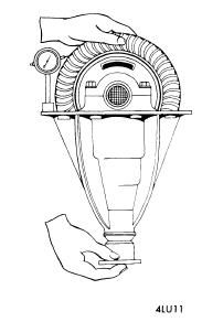
Installation - 1) If both axle shafts were removed ,isert a .079 (2 mm) shim between bearing holder and axle tube flange of first axle shaft to be installed. Insert shaft into axle tube and install and tighten bearing holder-to-flange bolts. For the second axle shaft (or if only on shaft was removed), insert shaft without shims into axle tube until it comes in contact with thrust block in differential. Measure clearance between bearing holder and axle tube flange (see illustration).
2) Proper size shim for this location may be determined by adding .004" (.1 mm) to measurement just obtained. Select a shim or combination of shims, withdraw axle shaft, and install shims between bearing holder and flange face. Reinstall axle shaft and tighte four though bolts. Connect brake line to wheel cylinder, then install brake shoed, parking brake cable, and brake drum. Install wheel and tire assembly, adjust broken and bleed system.
DIFFERENTIAL CARRIER
Removal and Installation - Raise rear of vehicle, remove wheels and brake drums, and disconnect brake lines at rear wheel cylinders. Disconnect parking brace cable brackets at rear spring locations, remove four through bolts from each end flange, and partially with draw axle shafts from axle tubes. Disconnect propeller shaft from pinion flange and place out of way. Remove nuts attaching carrier to axl housing and remove carrier assembly To install, reverse removal procedure, making sure to refill axle with lubricant.
OVERHAUL
Disassembly
 |
| REMOVING PINION SHAFT LOCK PIN |
1) Mark side bearing caps for reassembly reference, remove nuts and bearing caps, then remove differential case assembly. NOTE - Keep right and left side bearing races with respective bearings. Remove differential side bearings from case using a suitable puller and adapter (J-22888 and J-81072). Record thickness of each side bearing and each shim pack, then place with appropriate bearing race.
2) Remove ring gear bolts and separate ring gear from case. Drive out pinion shaft lock pin using a long drift. NOTE - It may be necessary to remove caulking in lock pin using a 5mm drill. Remove pinion shaft using a drift, then withdraw thrust block, pinion gears, side gears, and thrust washers.
3) Remove pinion nut and pinion flange. Drive the pinion gear from carrier using a soft hammer or drift. Withdraw front pinion bearing and oil seal. Using a drift, remove pinion bearing races from carrier. Mount pinion gear in a press and remove rear pinion bearing and depth shim from pinion gear.
REASSEMBLY AND ADJUSTMENT
Drive Pinion Depth - 1) Install front and rear pinion bearing races into carrier bores, lubricate pinion bearings, and position in respective races. Install a suitable gauging plate (J-23597-7) and preload stud and pilot (J-23597-9) through pinion bearings and tighten nut snugly. Rotate bearings to insure proper seating, then tighten lock nut until 20 in. lbs. (25 cmkg) of torque are required to rotate new bearings, or 8-10 In. Lbs. (9.2-11.5 cmkg) are required to rotate used bearings.
 |
| TOOL SETUP FOR MEASURING PINION DEPTH |
2) Place mounting discs (J-23597-8) onto arbot tool (J-23597-1) and place assembly in position in side bearing bores. Install bearing caps. Mount dial indicator on arbor post, preload dial 1/2 revolution, then tighten indicator in this position. Position indicator plunder on gauge plate, slowly swing across until highest reading of gauge plate. Swing plunger off gauge plate and note indicator reading. Reading is the correct thickness of rear pinion bearing depth shim for a nominal to .101". An indicator reading of .000" or .001" requires shims of .100" and .101" respectively.
3) Examine head of drive pinion; pinion depth code is stamped by chemical ink and is the lower of three numbers. A "+" (plus) number indicates need for greater mounting distance (decrease shim thickness), while a "-" (minus) number indicates need for smaller mounting distance (increased shim thickness). See following chart to determine proper shim variation to compensate for plus or minus markings. NOTE - If no pinion depth code is present, pinion is "nominal" and no correction to dial indicator reading is required.
Pinion code Correction Required
+10............................................ Subtract .005" (.13 mm)
+8.............................................. Subtract .004" (.10 mm)
+6.............................................. Subtract .003" (.08 mm)
+4.............................................. Subtract .002" (.03 mm)
+2.............................................. Subtract .001" (.03 mm)
0................................................ No Correction Required
-2............................................... Add .001" (.03 mm)
-4............................................... Add .002" (.05 mm)
-6............................................... Add .003" (.08 mm)
-8............................................... Add .004" (.10 mm)
-10............................................. Add .005" (.13 mm)
4) Place selected shim on drive pinion and press rear bearing on pinion. NOTE - Do not press on roller cage; press only on bearing inner race. Remove gauging tools from carrier.
Pinion Bearing Preload (W/ Solid Bearing Spacer) - 1) Place drive pinion and bearing spacer into carrier, then position original pinion shim and front pinion bearing over pinion gear. Install pinion flange and nut, tightening nut snugly. NOTE - Do not install oil seal at this time. Rotate bearing to insure proper seating, then tighten pinion nut to 190 ft lbs. (26.3 mkg). Wind a small amount of string (approximately 4-6 windings) around pinion flange. Using a pull scale, note pull scale reading required to rotate flange.
 |
2) Reading should be approximately 13-17 lbs. (5.9 - 7.7 kg) for new bearings, or 8-10 lbs (3.6-4.5 kg) for reused bearings. If necessary to adjust preload, remove nut and pinion flange and remove or install shims behind front bearing. Shim are available in thicknesses of .003" (.08 mm), .005" (.13 mm), and .010" (.25 mm). NOTE -To increase preload, decrease shim thickness; to decrease preload, increase shim thickness. When correct preload is obtained, remove pinion nut and flange, install oil seal, then reinstall flange using a new pinion nut.
Pinion Bearing Preload (W/Collapsible Bearing Spacer) - 1) Place drive pinion and collapsible spacer into carrier, then install front pinion bearing and oil seal. Mount pinion flange on drive pinion, apply lubricant to pinion threads, install pinion nut and tighten to 85 ft. lbs. (11.3 mkg). Rotate pinion to insure bearings are seated, then wind a small amount of string (approximately 4-6 windings) around pinion flange. Using a pull scale, note reading required to rotate flange.
2) Continue tightening nut in small increments until pull required to rotate flange in 17 lbs. (7.7 kg) for new bearings or 7-9 lbs (3.2-4.1 kg) for reused bearings. CAUTION - Preload builds quickly. Nut should be tightened only in small increments and pull scale used after each small amount of tightening. If preload is exceeded, a new collapsible bearing spacer must be intalled.

Case Assembly - Install side gears and thrust washers in case. Position thrust washers 180 degrees apart, then roll gears into position making sure they are in alignment to allow installation of pinion shaft. Place thrust block between pinion gears and drive pinion shaft into position, making sure roll pin hole aligns with hole in case. Measure backlash between side gears and pinion gears; if greater than .003" (.08 mm), install selective thrust washers to bring backlash within specifications. Washers are available in thicknesses of .037" (.94 mm), .041" (1.04 mm), and .045" (1.14 mm). NOTE - Increasing washer thickness decreases backlash; decreasing washer thickness increases backlash. Install lock pin into pinion shaft and caulk end to prevent loosening. Install ring gear into position on case, apply Lactite to bolt threads, and install and tighten ring gear to case bolts in a diagonal sequence.
Backlash & Side Bearing Preload - 1) If original side bearings, differential case, ring and pinion, and differential case, ring and pinion, and differential carrier are being reused, the original shims may be reinstalled in their respective positions. If only new side bearings are being installed, measure new bearings with a micrometer and compare thickness with original bearings. If new bearing is thicker, SUBTRACT difference from shim pack. If new bearing is thinner, ADD difference to shim pack.
 |
| CHECKING RING GEAR RUNOUT |
2) If new bearings and/or differential case, ring and pinion, or differential carrier are being installed, new shims must be selected as follows: Install side bearings onto differential case, but do not install shims at this time. Mount case into carrier bores. Move ring gear tightly against carrier on ring gear side (away from pinion), and hold in this position. Using a feeler gauge, measure clearance between bearing and differential carrier on side opposite ring gear. Record clearance.
3) A predetermined dimension (.018" on 1972 models, .002" on 1973 and later model(s) is needed to establish proper preload. Therefore, ADD this dimension to clearance obtained in this step 2) for proper preload. This will give necessary combined total thickness of both shim packs. Divide the total dimension into two packs equals the difference between original shim packs.
4) Remove case from carrier, remove side bearings and install shim packs, then reinstall bearings. Install differential case into carrier, tapping carefully into place. Install side bearing caps in original positions, install and tighten attaching bolts. Measure run-out of ring gear (see illustration). If run-out exceeds .002" (.05 mm), correct by cleaning or replacement of parts.
 |
| CHECKING RING AND PINION BACKLASH |
5) Mount a dial indicator against ring gear teeth and measure backlash in three locations. Backlash should be .005-.007 (.13-.18 mm): if not, shims behind side bearings must be adjusted. NOTE - To maintain preload when backlash is adjusted, the total thickness of both shim packs must not be altered. Therefore, if it is necessary to increase one shim pack, the opposite shim pack must be decreased by the same amount. To increase backlash, right side bearing shim must be increased, and left side decreased. To decrease backlash, rigth side shim must be decreased, and left side increased. NOTE - Backlash changes approximately .002" (.05 mm) for each .003 (.08 mm) shim change. After adjustment, make gear tooth pattern check to insure correct assembly.


