1975 Fiat Wheel Alignment Guide

FIAT SPECIFICATIONS AND ADJUSTMENT

TIRE INFLATION (COLD)
Before attempting to check or adjust wheel alignment, make sure tires are properly inflated. Refer to manufacturers specifications given in owner's manual.

CASTER
Model 131 and 128 (Except. Sport L) - If caster is not to specifications, raise front of vehicle. Remove stabilizer bar-to-control arm nut and disconnect control arm from body. Remove end of stabilizer bar from control arm. To adjust caster, addition of shims between end of stabilizer bar and rubber pad of control arm will decrease caster angle and removal of shims will increase caster angle. Reverse removal procedure and recheck caster.

Model 128 Sport L - If caster is not to specifications, adjust by adding or removing shims located between stabilizer bar bushing and frame.

Model 124 - If caster is not within specifications, raise front of vehicle and remove wheel and shock absorber. Using suitable tool (A.74174), compress spring to relieve lower control arm and loosen nuts holding control arm pivot bar to crossmember. To adjust caster, remove shims from front stud and move to rear stud to increase caster. To decrease caster, remove shims from rear stud and move shims to front stud. Reverse removal procedure and check caster.

Model X1/9 - If caster is not to specifications, adjust by adding or removing shims located between stabilizer bar and stabilizer bar support.

CAMBER
Model 124 - If camber is not within specifications, adjust by changing shims. Raise front of vehicle, remove wheel and shock absorber. Using suitable tool (A.74174), compress spring to relieve lower control arm and loosen nuts holding control arm pivot bar to crossmember. To increase camber, remove equal amount of shims from both studs and add equal amount of shims to decrease camber. NOTE -  Adding or removing equal amounts of shims will not affect caster. Reverse removal procedure and check camber.

Model 128 and 131 Front - Camber is nonadjustable. If not within specifications, inspect suspension for damage and repair or replace parts as necessary.

Model 128 Rear - If rear camber is not within specifications raise rear of vehicle and compress one end of leaf spring, shifting it from flexible guide anchoring spring to control arm. Remove guide and slowly release spring. Remove nuts attaching pivot to body and loosen screw to free adjustment shims. To increase camber, add an equal number of shims on both screws attaching control arm to body. To decrease, remove equal number of shims from both screws. Reverse removal procedure and check camber.

Model X1/9 Front and Rear - Camber is nonadjustable. If not within specifications, inspect suspension for damage and repair or replace parts as necessary.

TOE-IN
Model 128, 131 and X1/9 Front - Place front wheels in straight-ahead position. If toe-in is not within specifications, loosen sleeve locking nut on tie rods. To adjust, rotate hexagon on ball pin to set toe-in specifications. Hold hexagon in position and lock nut against tie rod sleeve.

Model 128 Rear - If rear toe-in is not within specifications raise rear of vehicle and compress one end of leaf spring, shifting it from flexible guide anchoring spring to control arm. Remove guide and slowly release spring. Remove nuts attaching pivot to body and loosen screws to free adjustment shims. To increase to-in, add shims to rear screw or remove shims front front screw. To decrease, add shims to front screw or re3move shims from rear screw.

Model 124 Front - Place front wheels in straight-ahead position. If toe-in is not within specifications, loosen four clamps securing sleeves on tie rods. Rotate tie rods in opposite direction (by equal amounts) to set toe-in to specifications. Tighten clamp nuts. NOTE - Expansion slot in sleeve must coincide with clamp joint when clamp is fully tightened.

Model X1/9 Rear - If rear toe-in is not within specifications, loosen clamps securing sleeves to reaction rods. Adjust toe-in by lengthening or shortening reaction rods. Tighten clamps and recheck toe-in.


1963-73 Fiat Models Wheel Alignment Guide

1963-73 FIAT SPECIFICATIONS AND ADJUSTMENTS

TIRE INFLATION (COLD)
Before attempting to check or adjust wheel alignment, ensure that tires are inflated according to specifications


CASTER
Model 128 - If caster is not within specifications, raise front of vehicle. Remove anti-roll bar to control arm nut and disconnect control arm from body. Remove end of anti-roll bar from control arm. To adjust caster, addition of shims between end of anti-roll bar and rubber pad of control arm will decrease caster and removal of shims will increase caster. Reverse removal procedure and check caster.

Model 124 - If caster is not within specifications, raise front of vehicle and remove wheel and shock absorber. Using suitable tool (A.741174), compress spring to relieve lower control arm and loosen nuts holding control arm pivot bar to crossmember. To adjust caster, remove shims from front stud and move to rear stud to increase caster. To decrease caster, remove shims from rear stud and move shims to front stud. Reverse removal procedure and check caster.

Models 600D, 850 and 1100R - If caster is not within specifications, loosen two nuts on control arm pivot bar to body. To adjust, remove shims from rear stud and place shims at front stud to increase caster. To decrease caster, move shims from front stud to rear stud. Tighten nuts and check caster.

Model 1500 - No adjustment procedure available.

CAMBER
Model 124 - If camber is not within specifications, adjust by changing shims. Riase front of vehicle, remove wheel and shock absorber. Using suitable tool (A.74174), compress spring to relieve lower control arm and loosen nuts holding control arm pivot bar to crossmember. To increase camber, remove equal amount of shims from both studs and add equal amount of shims to decrease camber. NOTE - Adding or removing equal amounts of shims will not affect caster. Reverse removal procedure and check camber.

Model 1500 - No adjustment procedure available at time of this publication. See Wheel Alignment specifications.


Model 128 - Front - Camber is nonadjustable. If not within specifications, inspect suspension for damage. Repair or replace parts as necessary.

Model 128 Rear - If rear camber is not within specifications raise rear of vehicle and compress one end of leaf spring, shifting it from flexible guide anchoring spring to control arm. Remove guide and slowly release spring. Remove nuts attaching pivot to body and loosen screw to free adjustment shims. To increase camber, add an equal number of shims on both screws attaching control arm to body. To decrease, remove equal number of shims from both screws. Reverse removal procedure and check camber.

Models 600D, 850 and 1100R Front - If camber is not within specifications, adjust by changing shims. Loosen two nuts on control arm pivot bar to body. To increase camber, add equal amounts of shims to both studs and to decrease, remove equal amounts of shims. Tighten nuts and check camber.

TOE-IN
Model 128 Front - Place front wheels in straight-ahead position. If toe-in is not within specifications, loosen sleeve locking nut on tie rods. To adjust, rotate hexagon on ball pin to set toe-in specifications. Hold hexagon in position and lock nuts against tie rod sleeve.

Model 128 Rear - If rear toe-in is not within specifications raise rear of vehicle and compress one end of leaf spring, shifting it from flexible guide anchoring spring to control arm. Remove guide and slowly release spring. Remove nuts attaching pivot to body and loosen screws to free adjustment shims. To increase toe-in, add shims to rear screw or remove shims from front screw. To decrease, add shims to front screw or remove shims from rear screw.

All Other Models Front - Place front wheels in straight ahead position. If toe-in is not within specifications, loosen four clamps securing sleeves on tie rods. Rotate tie rods in opposite direction (by equal amounts) to set toe-in to specifications. Tighten clamps. NOTE - Expansion slot in sleeve must coincide with clamp joint when clamp is fully tightened.

Model 600D and 850 Rear - If rear is not within specifications, loosen screws securing lower control arm support to body. Elongated holes on support allow movement to set toe-in to specifications. Tighten screws 29-36 ft lbs. and check toe-in.

1974-75 Nissan Datsun Wheel Alignment Guide

DATSUN SPECIFICATIONS AND ADJUSTMENTS

TIRE INFLATION (COLD)
Before attempting to check or adjust wheel alignment, make sure that tires are properly inflated. Refer to manufacturer's specifications given in owner's manual.

RIDING HEIGHT
Pickup Only - Measure distance from center of lower control arm bushing (where it connects to body) and lower steering knuckle bushing (see illustration). To adjust, raise vehicle to release tension on anchor bolt adjusting nut and turn anchor bolt to adjust to specified height.

             Riding Height Specifications
Application                                   Inches (mm)
620 Pickup................................  3.1-3.2 (72-82)

CASTER
All Models Exc. Pickup - Preset at factory and cannot be adjusted. If not to specifications, check suspension for wear or damage and repair or replace components as necessary.

Pickup - Caste is adjusted by increasing or decreasing thickness of shims inserted between upper link spindle and upper link mounting bracket. When front shim thickness increases, caster decreases. NOTE - Do not adjust caster with difference between front and rear shim thicknesses beyond .078" (2mm).

CAMBER
All Models (Exc. Pickup) - Preset at factory and cannot be adjusted. If not to specifications, check suspension for wear or damage and repair or replace components as necessary.

Pickup - Camber is adjusted bye increasing or decreasing the thickness of shims inserted between upper link spindle and upper link mounting bracket. When thickness of shims increase, camber decreases.


TOE-IN
All Models - Adjust by loosening each side steering link lock nut and adjusting steering link to change toe-in.
NOTE - Left and right side steering links should be adjusted equally. Tighten lock nuts.

1974 Datsun Models

1975 Nissan Datsun

1962-72 Nissan Datsun Wheel Alignment Guide

1962-72 DATSUN SPECIFICATIONS AND ADJUSTMENTS
TIRE INFLATION (COLD)
Before attempting to check or adjust wheel alignment, ensure that tires are properly inflated.


RIDING HEIGHT
Pickups Only - Adjust to specificied distance by turning anchor bolt adjusting nut. Raise vehicle to release tension on adjusting nut.

Riding Height Measuring Point


CASTER
All Models (Except 240Z, 510 and 1200) - Caster is adjusted by increasing or decreasing the thickness of shims inserted between upper link spindle and upper link mounting bracket. When front shim thickness increases, caster reduces. Set caster to specifications given in table. NOTE - Do not adjust caster with difference between front and rear shim thicknesses beyond .078".

240Z, 510 and 1200 - Caster is not adjustable. If alignment is not within specifications, check for damaged parts and replace as necessary

CAMBER
All Models (Except 240Z, 510 and 1200) - Camber is adjusted by increasing or decreasing the thickness of shim inserted between upper link spindle and upper link mounting bracket. When thickness of shims increases, camber reduces. Set camber to specifications given in table.

240Z, 510 and 1200 (Front) - Camber is not adjustable. If alignment is not within specifications, check for damaged parts and replace as necessary.

240Z and 510 (Rear) - Camber is not adjustable. If alignment is not within specifications, check for damaged parts and replace as necessary.

TOE-IN
All Models (Except Pickups) - Adjust by loosening side rod lock nuts and adjusting length of side rod to change toe-in to correct specifications. NOTE - Left and right side rods should be moved equally. Tighten lock nuts.

Pickups - Adjust by loosening cross rod lock nuts and turning cross rod to change its length which will increase or decrease the toe-in depending on the direction rod is turned. With toe-in to correct specifications, tighten lock nuts.


1971-72 Cricket Wheel Alignment Guide

1971-72 CRICKET SPECIFICATIONS AND ADJUSTMENTS

TIRE INFLATION
Before attempting to check or adjust front wheel alignments, ensure tires are properly inflated. Manfucturer recommended tire pressure is stenciled on inside of glove box door.

CASTER
Caster is not adjustable. If alignment is not within specification, inspect for damage parts and replace as necessary.

CAMBER
Camber is not adjustable. If alignment is not within specifications, inspect for damaged parts and replace as necessary.

TOE-IN
To adjust toe-in, loosen ball joint lock nuts on both tie rods. Loosen screws in rubber boot on inner ends of tie rod and ensure boots are free. Adjust tie rods to specifications (see chart). Tighten lock nut on tie rod end joints and center tie rods. Align boots and tighten clamps until boots are secure.


1972-76 Courier All Models Wheel Alignment Guide

1972-73 COURIER SPECIFICATIONS AND ADJUSTMENTS

TIRE INFLATION
Before attempting caster or camber adjustments, ensure tires are correctly inflated. Specifications are located on glove box door; especially consider radial tires, they require a different pressure than conventional tires.
NOTE - For reliable vehicle control, maintain specified difference between front and rear tire pressure.
NOTE - Vehicle must be unloaded, except fuel, water, and oil should be at their proper levels.

CASTER
To correct caster, adjust shims between upper control arm and frame or turn control arm shaft until correct angle is obtained (see specifications).

CAMBER
The camber is adjusted by adding or subtracting shims between the upper control arm and frame. Shims are available in the following sizes: .040", .064", .080", and .128". Set camber to specifications as shown in chart.

TOE-IN
The upward pointing of both front wheels which is necessary at offset the effects of camber. To adjust proceed as follows.

1) Raise vehicle until front wheels clear ground. Turn wheel by hand and scribe a line in cenber of each tire tred. Measure distance between marked lines. Both measurements must be taken at equal distances from ground.

2) If distance between wheels at rear is greater than that at front, but within specifications, adjustment is correct. If adjustment is wrong, loosen clamp bolts and adjust tie rod to specifications.
NOTE - Tighten clamping bolts with bolts horizontal and below steering link to prevent interference with center steering link.

FRONT WHEEL TURNING ANGLE
Front wheels should turn 37 degrees inward and 32 degrees outward. If necessary, adjust stop screws located at steering knuckle.

1972-73 Courier Models

1974-75 Courier Models


1971-75 Colt All Models Wheel Alignment

COLT SPECIFICATIONS AND ADJUSTMENTS

TIRE INFLATION (COLD)
Before attempting to check or adjust wheel alignment, ensure that tires are properly inflated. Refer to specifications in owners handbook.

CASTER
Caster is nonadjustable. If not within specifications, check front suspension for damage. Repair or replace parts as necessary.

CAMBER
Camber is nonadjustable. If not within specifications, check front suspension for damage. Repair or replace parts as necessary.

TOE-IN
Position wheels in straight-ahead position. If toe-in is not within specifications, loosen locking nuts on tie rod turn buckels. To adjust, rotate turn buckels until toe-in is within specifications. Tighten lock nuts. NOTE - Adjustment must be made equally to both sides of vehicle to maintain correct wheel lock angles; difference of tie rod length when adjusted should not exceed. 20".

1971-73 Colt Models

1974 Colt Models

1975 Colt All Models


Suzuki Samurai SQ420WD Repair Manual

Manufacturer: Suzuki
Model: Samurai SQ420WD


Contains the following information and repairs for:

  • General Information
    • Maintenance and Lubrications
  • Heating and Air Conditioning
  • Steering, Suspension, Wheels and Tires
    • Power Steering (P/S) System
  • Drive Shaft / Propeller Shaft
    • Front Drive Shaft / Shaft Bearing, Oil Seal
  • Engine
    • General Information and Diagnosis
    • Engine Mechanical (RF)
    • Engine Cooling
    • Engine Fuel
    • Engine and Emission Control System
      • Electronically Controlled Diesel Fuel Injection System
    • Charging System
    • Exhaust System
  • Transmission, Clutch and Differential
    • Automatic Transmission
    • Clutch (Hydraulic Type)
    • Differential (Rear)
  • Body Electrical System
    • Instrumentation / Driver Information
    • Immobilizer Control System
  • Service Data
  • Wiring Diagrams
File Size: 61 MB
File Type: PDF, RAR

Suzuki Webber Carburetors

Manufacturer: Suzuki
Model: Webber


Repair Manual for Redline and Webber Carburetors

  • Redline Webber Typical DGV Carb Install Views
  • 32/36 DGEV-DGAV

File Size: 17 MB
File Type: PDF, RAR

Suzuki Sierra SJ 413 Repair Manual

Manufacturer: Suzuki
Model: Sierra SJ 413


Contains the following information and repairs for:

  • General, Special Tools and Service Materials
  • Periodic Maintenance Service
  • Trouble Shooting
  • Engine
  • Fuel System
  • Emission Control System
  • Engine Cooling System
  • Car Heater
  • Ignition System
  • Cranking System
  • Charging System
  • Clutch
  • Gear Shifting Control
  • Transmission
  • Transfer Gear Box
  • Propeller Shafts
  • Differential
  • Suspension
  • Steering System
  • Brakes
  • Body Service
  • Body Electrical Equipment
  • Service Data
  • Wiring Diagrams
File Size: 70 MB
File Type: PDF, RAR

Suzuki LJ80 Repair Manual

Manufacturer: Suzuki
Model: LJ80


Contains the following information and repairs for:

  • General, Special Tools and Service Materials
  • Trouble Shooting
  • Engine
  • Carburetor
  • Air Cleaner, Fuel Pump and Filter
  • Engine Cooling System
  • Car Heater
  • Ignition System
  • Starter Motor
  • Charging System
  • Clutch
  • Gear Shifting Control
  • Transmission
  • Transfer Gear Box
  • Propeller Shafts
  • Differential
  • Suspension
  • Steering System
  • Brakes
  • Door and Tarp Top
  • Body Electrical Equipment
  • Service Data and Maintenance Schedules
  • Others
File Size: 19 MB
File Type: PDF, JPG

Suzuki Swift GTi 1989 Repair Manual

Manufacturer: Suzuki
Model: Swift GTi 
Year: 1989


Contains the following information and repairs for:

  • General Information
  • Heating and Air Conditioning 
  • Bumper and Sheet Metal
  • Steering, Suspension, Wheels and Tires
    • Front End Alignment
    • Manual Rack and Pinion
    • Steering Wheel and Column
    • Front and Rear Suspension
    • Wheel and Tires
  • Drive Shaft
    • Front Drive Shaft (Double Offset Joint Type)
    • Front Drive Shaft (Tripod Joint Type)
  • Brakes
  • Engine 
    • Diagnosis
    • Engine Mechanical
    • Engine Cooling
    • Engine Fuel
    • Electronic Fuel Injection (EFI) System
    • Ignition System
    • Cranking System
    • Charging System
    • Emission Controls
    • Exhaust System
  • Transmission and Clutch
    • Manual and Automatic Transmission
    • Clutch
  • Body Electrical System
  • Body Service
File Size: 109 MB
File Type: PDF, RAR

Suzuki Samurai & Sidekick GEO Tracker Repair Manual

Manufacturer: Suzuki
Model: Samurai and Sidekick GEO Tracker 
Year: 1986 to 1996


Contains the following information and repairs for:

  • Tune-up and Routine Maintenance
  • Engine
  • General Engine Overhaul Procedures
  • Cooling, Heating and Air Conditioning Systems
  • Fuel and Exhaust Systems
  • Engine Electrical Systems
  • Emissions Control Systems
  • Manual Transmission
  • Automatic Transmission
  • Transfer Case
  • Suspension and Steering Systems
  • Body
  • Chassis Electrical System
  • Wiring Diagrams
File Size: 60 MB
File Type: PDF, RAR

Suzuki Samurai SJ Repair Manual

Manufacturer: Suzuki
Model: Samurai


Contains the following information and repairs for:

  • General, Special Tools and Service Materials
  • Periodic Maintenance Service
  • Trouble Shooting
  • Engine
  • Fuel System (Carburetor, Air Cleaner, Fuel Pump, and Fuel Filter)
  • Emission Control System
  • Engine Cooling System
  • Car Heater
  • Ignition System
  • Cranking System
  • Charging System
  • Clutch
  • Gear Shifting Control
  • Transmission
  • Transfer Gear Box
  • Propeller Shafts
  • Differential
  • Suspension
  • Steering System
  • Brakes
  • Body Service
  • Body Electrical Equipment
  • Service Data
File Size:
File Type: PDF, RAR

Suzuki Samurai SJ 1987 Repair Manual

Manufacturer: Suzuki
Model: Samurai


Contains the following information and repairs for:

  • General, Special Tools and Service Materials
  • Periodic Maintenance Service
  • Trouble Shooting
  • Engine
  • Fuel System (Carburetor, Air Cleaner, Fuel Pump, and Fuel Filter)
  • Emission Control System
  • Engine Cooling System
  • Car Heater
  • Ignition System
  • Cranking System
  • Charging System
  • Clutch
  • Gear Shifting Control
  • Transmission
  • Transfer Gear Box
  • Propeller Shafts
  • Differential
  • Suspension
  • Steering System
  • Brakes
  • Body Service
  • Body Electrical Equipment
  • Service Data
File Size: 228 MB
File Type: PDF, RAR

Suzuki SX4 2007 Repair Manual

Manufacturer: Suzuki
Model: SX4 RW415, RW416 and RW420
Year: 2007


Contains the following information and repairs for:

  • General Information
  • Heating and Air Conditioning
    • Heater and Ventilation
    • Air Conditioning
  • Steering, Suspension, Wheels and Tires
    • Wheel Alignment
    • Manual Rack and Pinions
    • Electrical Power Steering (P/S) System
    • Steering Wheel and Column
    • Front Suspension
    • Rear Suspension
    • Wheel and Tires
  • Driveshafts and Propeller Shaft
  • Brakes System
    • Anti-Lock Braking System (ABS)
  • Engine
    • Engine Mechanical
    • Engine Cooling
    • Engine Fuel
    • Engine and Emission Control System
    • Ignition System
    • Cranking System
    • Charging System
    • Exhaust System
  • Transmission and Differential
    • Manual Transmission
    • Clutch
    • Differential
  • Electrical System
    • Wiring Diagrams
  • Restraint System
    • Restraint System
    • Air Bag System
File Size: 202 MB
File Type: PDF, RAR

Suzuki Grand Vitara 2005 Repair Manual

Manufacturer: Suzuki
Model: Vitara JB416 and JB420
Year: 2005


Contains the following information and repairs for:

  • General Information
    • Maintenance and Lubrication
  • Engine
    • Precautions
    • Engine General Information and Diagnosis
    • Auxiliary Emission Control Devices
    • Engine Electrical Devices
    • Engine Mechanical
    • Engine Lubrications System
    • Engine Cooling System
    • Fuel System
    • Ignition System
    • Starting System
    • Charging System
    • Exhaust System
  • Suspension
    • Suspension General Diagnosis
    • Front and Rear Suspension
    • Wheels and Tires
  • Driveline/ Axle
    • Drive Shaft / Axle
    • Differential
    • Transfer
    • Propeller Shafts
  • Brake
    • Brake Control System and Diagnosis
    • Front and Rear Brakes
    • Parking Brakes
    • ABS
  • Transmission / Transaxle
    • Manual and Automatic Transmission / Transaxle
    • Clutch
  • Steering
    • Steering General Diagnosis
    • Steering Wheel and Column
    • Power Assisted Steering System
  • HVAC
    • Heater and Ventilation
    • Air Conditioning System
  • Restraint
    • Seat Belts
    • Air Bag System
  • Body, Cab and Accessories
    • Wiring Systemss
    • Lighting Systems
    • Instrumentation/ Driver Info. / Horn
    • Wipers / Washers
    • Glass / Windows / Mirrors
    • Security and Locks
    • Seats
    • Interior Trim
    • Sunroof / T-Top / Convertible Top
    • Hood / Fenders / Doors
    • Body Structure
    • Paint / Coatings
    • Exterior Trim
  • Control Systems
    • Cruise Control Systems
    • Body Electrical Control Systems
    • Immobilizer Control Systems
    • Keyless Start System
File Size:
File Type: PDF

Suzuki Samurai 1988 Repair Manual

Manufacturer: Suzuki
Model: Samurai
Year: 1988


Contains the following information and repairs for:

  • General, Special Tools and Service Materials
  • Periodic Maintenance Service
  • Troubleshooting
  • Engine
  • Fuel System 
    • Carburetor, Air Cleaner, Fuel Pump and Fuel Filter
  • Emission Control System
  • Engine Cooling System
  • Car Heater
  • Ignition System
  • Cranking System
  • Charging System
  • Clutch
  • Gear Shifting Control
  • Transmission
  • Transfer Gear Box
  • Propeller Shafts
  • Differential
  • Suspension
  • Steering System
  • Brakes
  • Body Service
  • Body Electrical Equipment
  • Service Data
File Size: 81 MB
File Type: PDF, RAR

Suzuki Swift 2004-2008 Repair Manual

Manufacturer: Suzuki
Model: Swift 2nd Generation
Year: 2004 to 2008


Contains the following information and repairs for:

  • General Information
  • Engine
    • Precautions
    • Engine General Information and Diagnosis
    • Aux. Emission Control Devices
    • Engine Electrical Devices
    • Engine Mechanical
    • Engine Lubrication System
    • Engine Cooling System
    • Fuel System
    • Ignition System
    • Starting System
    • Charging System
    • Exhaust System
  • Suspension
    • Precautions
    • Suspension General Diagnosis
    • Front Suspension
    • Rear Suspension
    • Wheels and Tires
  • Driveline/ Axle
    • Drive shaft / Axle
  • Brakes
    • Brake Control System and Diagnosis
    • Front Brakes
    • Rear Brakes
    • Parking Brake
    • ABS
    • Electronic Stability Program
  • Transmission/Transaxle
    • Automatic Transmission/Transaxle
    • Manual Transmission/Transaxle
    • Clutch
  • Steering 
    • Steering General Diagnosis
    • Steering Wheel and Column
    • Power Assisted Steering System
  • HVAC
    • Heater and Ventilation
    • Air Conditioning System
  • Restraint
    • Seat Belts
    • Air Bag System
  • Body, Cab and Accessories
    • Wiring Systems
    • Lighting Systems
    • Instrumentation/ Driver Info/ Horn
    • Wipers/Washers
    • Glass/ Windows/ Mirrors
    • Security and Locks
    • Seats
    • Interior Trim
    • Hood/ Fenders/ Doors
    • Body Structure
    • Paint/ Coatings
    • Exterior Trims
  • Control Systems
    • Body Electrical Control Systems
    • Immobilizer Control Systems
    • Keyless Start System
File Size: 54 MB
File Type: PDF, RAR

1974 Vehicles Ball Joint Checking

ALFA ROMEO
All Models - Check working surfaces of ball pins and their seats, and ball joint studs for damage or wear. Axial play should not exceed specifications (.04"). Replace complete ball joint unit when indicated.

BMW
All Models - With lower control arm removed, measure axial (up and down) movement of ball joint stud. If movement exceeds .0945", replace ball joint. See BMW in SUSPENSION Section.

CAPRI
All Models - To check ball joint wear, raise vehicle and attach a dial indicator to a suitable fixed pivot, with stem on ball joint cap. Raise wheel independently of vehicle and note maximum dial gauge reading. If gauge reading is in excess of .098", ball joint should be replaced.

COLT
All Models - With components removed from control arm and ball joint still installed, check the following: Horizontal and vertical free play (0"), and ball joint rotation starting torque 4-7 ft. lbs. (.6-1.0 mkg). Replace ball joints if correct specifications are not obtained.

DATSUN
All Models (Exc. 620 Pickup) - Remove lower control arm. See Datsun in SUSPENSION Section. Measure axial movement by lifting and depressing ball joint stud. Difference between these two measurements is axial movement. Using suitable spring tension gauge attached to top of ball joint stud, measure force (ft. lbs.) required to move ball joint stud laterally. If either measurement is not within specifications, replace ball joint.

Ball Joint Specifications
Application                                      Axial                                      Lateral
                                                                                         INCH Lbs. (cmkg)
B210............................    .004-.012" (.1-.3mm)................................52 (60)
610 & 710....................   .004" (.1 mm) ...................................35 (40)
260Z.............................   .001-.024" (.03mm-.6mm).....................................

FIAT
All Models - With vehicle raised and supported under lower control arms, grasp wheel at top and bottom and try to shake wheel. If any movement is noted, control ar must be removed for further inspection. See Fiat in SUSPENSION Section.

HONDA
Raise and support front of vehicle. Attach dial indicator onto lower control arm with indicator tip on steering knuckle near ball joint. Place pry bar between lower control arm and steering knuckle. NOTE - Take care not to damage ball joint rubber boot. Push on pry bar and observe movement on dial indicator. If any movement is noted on dial indicator, ball joint must be replaced. See Honda in SUSPENSION Section.

JAGUAR
All Models (Exc. "E" Type Series 3) - Upper ball joint must be replaced if signs of wear or play are evident. The lower ball joint is adjustable with shims if axial play exceeds .004-.006". Shims must not be removed to take up excessive wear in ball pin and socket. If parts are badly worn, replacement is required.

"E" Type Series 3 - Upper and lower ball joints are adjustable by using shims to keep play within limits. Lower ball joint should have .004-.006" axial play and upper ball joint should have .004" axial play. Shims should not be removed to take up excessive wear in ball pin and socket. If parts are worn, replacement is required.

JENSEN-HEALEY
Raise front of vehicle and support under each lower control arm. Grasp wheel at top and bottom and try to shake wheel. NOTE - Do not confuse axial play of wheel bearing with worn ball joints. If any looseness is observed, ball joints should be replaced. See Jensen - Healey in SUSPENSION Section.

LUV
With vehicle raised and supported under lower control arms grasp wheel at top and bottom. Try to shake wheel and if any movement is noted, inspect front suspension of wear or damage.

MAZDA
All Models  (Exc. Pickup) - Check ball joint dust seal for wear or damage and, if necessary, replace seal. Check ball joint for wear or looseness by disconnecting each tie rod and attaching a pull scale to tie rod hole in spindle arm. If this measurement is not within 27-40 lbs. (12-18 KG) or 13-22 lbs. (6-10 kg) all other it will be necessary to replace ball joint.

Mazda (Pickup) - Check ball joint dust seal for wear or damage and, if necessary, replace seal. Ball joint end play is preadjusted at factory to be from 0-.08" (0-2 mm). If end play exceeds specifications, replace ball joint in its assembled form.

OPEL
All Models - Raise and support front of vehicle. Inspect ball joint rubber boots for damage and replace as necessary. Using suitable gauge (J-23745) measure axial play. If axial play is more than .080" (2 mm), ball joint must be replaced.


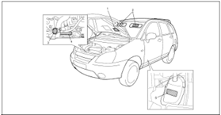
Suzuki Liana Aerio Repair Manual

Manufacturer: Suzuki
Model: Liana Aerio
Year: 2001 to 2007


Contains the following information and repairs for:

  • General Information
    • Maintenance and Lubrication
  • Heating and Air Conditioning 
    • Heater and Ventilation
    • Air Conditioning
  • Steering, Suspension, Wheels and Tires
    • Steering, Suspension, Wheel and Tires
    • Wheel Alignment
    • Manual Rack and Pinion
    • Electrical Power Steering (P/S) System
    • Steering Wheel and Column
    • Front and Rear Suspension
    • Wheel and Tires
  • Drive Shafts and Propeller Shaft
    • Propeller Shaft
  • Brake System
    • Brakes System
    • Anti-Lock Brake System (ABS)
  • Engine
    • Engine Mechanical
    • Engine Cooling
    • Engine Fuel
    • Engine and Emission Control Systems
    • Ignition System
    • Cranking System
    • Charging System
    • Exhaust System
  • Transmission Clutch and Differential
  • Electrical System
  • Body Service
  • Restraint System
    • Airbag System
File Size: 37 MB
File Type: PDF, RAR

Subaru Forester SF Repair Manual


Manufacturer: Subaru
Model: Forester SF
Year: 1999 to 2002

Contains the following information and repairs for:

  • Body
    • Air Bag System
    • Body Structure
    • Communication System
    • Cruise Control System
    • Entertainment
    • Exterior Body Panels
    • Exterior Interior Trim
    • Glass Windows Mirrors
    • HVAC System (Auto AC) Diagnosis
    • HVAC System (Heater Ventilator and A/C)
    • Immobilizer
    • Instrumentation Driver Information
    • Lighting System
    • Occupant Detection System Diagnosis
    • Seat Belt Systems
    • Seats
    • Security and Locks
    • Sunroof
    • Wiper and Washer System
  • Chassis
    • ABS Diagnosis
    • Brake
    • Differential
    • Drive Shaft System
    • Front and Rear Suspension
    • Parking Brake
    • Power Steering
    • Transfer Case
    • VDC Diagnosis
    • Vehicle Dynamics Control
    • Wheel and Tire
  • Engine (H4DOTC and H4SO)
    • Cooling
    • Emission Control
    • Engine Diagnostics
    • Exhaust
    • Fuel Injection
    • General Description
    • Ignition 
    • Intake
    • Lubrication
    • Mechanical
    • Speed Control
    • Starting and Charging Systems
  • Transmission
    • Automatic Transmission Diagnostics
    • Clutch System
    • Control System
    • Manual Transmission and Differential
  • Wiring Diagrams
  • TSB
  • Tech Reference Booklets
File Size: 42 MB
File Type: PDF, RAR

Subaru Forester SG 2003-04 Repair Manual

Manufacturer: Subaru
Model: Forester SG 
Year: 2003 to 2004


Contains the following information and repairs for:


  • Body
    • Air Bag System
    • Body Structure
    • Communication System
    • Cruise Control System
    • Entertainment
    • Exterior Body Panels
    • Exterior Interior Trim
    • Glass Windows Mirrors
    • HVAC System (Auto AC) Diagnosis
    • HVAC System (Heater Ventilator and A/C)
    • Immobilizer
    • Instrumentation Driver Information
    • Lighting System
    • Occupant Detection System Diagnosis
    • Seat Belt Systems
    • Seats
    • Security and Locks
    • Sunroof
    • Wiper and Washer System
  • Chassis
    • ABS Diagnosis
    • Brake
    • Differential
    • Drive Shaft System
    • Front and Rear Suspension
    • Parking Brake
    • Power Steering
    • Transfer Case
    • VDC Diagnosis
    • Vehicle Dynamics Control
    • Wheel and Tire
  • Engine (H4DOTC and H4SO)
    • Cooling
    • Emission Control
    • Engine Diagnostics
    • Exhaust
    • Fuel Injection
    • General Description
    • Ignition 
    • Intake
    • Lubrication
    • Mechanical
    • Speed Control
    • Starting and Charging Systems
  • Transmission
    • Automatic Transmission Diagnostics
    • Clutch System
    • Control System
    • Manual Transmission and Differential
  • Wiring Diagrams
  • TSB
  • Tech Reference Booklets
File Size: 68 MB
File Type: PDF, RAR

    Subaru Impreza 2002 GD GG Repair Manual

    Manufacturer: Subaru
    Model: Impreza GD GG
    Year: 2002


    Contains the following information and repairs for:

    • General Information
    • SOHC Engine and DOHC Engine
      • Fuel Injection System
      • Emission Control
      • Intake (Induction)
      • Mehcanical
      • Exhaust
      • Cooling
      • Lubrication
      • Speed Control System
      • Ignition
      • Starting/Charging System
      • Engine Diagnostics
    • Transmission
      • Control Systems
      • Automatic Transmission Diagnostics
      • Manual Transmission
      • Clutch
    • Chassis
      • Front and Rear Suspension
      • Wheel and Tire System
      • Differentials
      • Transfer Case
      • Drive Shaft System
      • ABS Diagnostics
      • Brakes
      • Parking Brake
      • Power Assisted Systems
    • Body
      • HVAC System Heater, Ventilator and A/C
      • Airbag System Diagnostic
      • Seat Belt System
      • Lighting System
      • Wiper and Washer Systems
      • Entertainment
      • Communication System
      • Glass, Windows and Mirrors
      • Body Structure
      • Instrumentation
      • Seats
      • Security and Locks
      • Exterior and Interior Trim
      • Exterior Body Panels
      • Cruise Control Systems Diagnostics
      • Option Parts
    • Wiring Diagrams
    • Car Information
    File Size:
    File Type: PDF, RAR

    Subaru Impreza 1993-96 Repair Manual

    Manufacturer: Subaru
    Model: Impreza
    Year: 1993 to 1996


    Contains the following information and repairs for:

    • General Information
      • Specifications
      • Pre-Delivery Inspection
      • Periodic Maintenance Services
      • Special Tools
    • Engine
      • On-Car Services
      • Engine (DOHC)
      • Engine Lubrication System
      • Fuel Injection System (MFI-Turbo)
      • Fuel System
      • Exhaust System
      • Clutch
      • Engine and Transmission Mounting System
    • Transmission and Differential
      • Manual Transmission and Differential
      • Automatic Transmission and Differential
      • AWD Systems
    • Mechanical Components
      • Suspension
      • Wheel and Axles
      • Steering System
      • Pedal System and Control Cables
      • Air Conditioning System
    • Body
      • Body and Exterior
      • Instrument Panel
      • Supplemental Restraint System
    • Electrical
      • Body Electrical System
    • Diagnosis
    • Wiring Diagrams
    File Size:  43 MB
    File Type: PDF, RAR

    Subaru Impreza 1997-98 Repair Manual

    Manufacturer: Subaru
    Model: Impreza GC, GF, GM
    Year: 1997 to 1998


    Contains the following information and repairs for:

    • General Information
      • Specifications
      • General Information
      • Periodic Maintenance Services
    • Engine
      • Emission Control System and Vacuum Fitting 
      • Engine Section
      • Engine Cooling System
      • Exhaust System
      • Fuel Injection System
      • Fuel System
    • Transmission and Differential Section
      • Clutch
      • Manual Transmission and Differential
      • AWD System
    • Mechanical Components
      • Suspension
      • Wheels and Tires
      • Steering System
      • Braking System
      • Pedal and Control Cables
      • Heater and Ventilator
      • Air Conditioning System
    • Body and Exterior
      • Doors and Windows
      • Supplemental Restraint System
    • Diagnosis - Body Electrical
      • Engine Electrical
      • Body Electrical
      • Wiring Diagrams
    File Size: 169 MB
    File Type: PDF, RAR

    Subaru Impreza 2004 STi Repair Manual

    Manufacturer: Subaru
    Model: Impreza GD

    Year: 2004


    Contains the following information and repairs for:

    • General Information
      • Foreword
      • How to use this Manual
      • Specifications
      • Preacaution
      • Note
      • Identification
      • Recommended Materials
      • Pre-Delivery Inspection
      • Periodic Maintenance Services
    • Engine Section
      • Fuel Injection (Fuel Systems)
      • Emission Control (Aux. Emission Controls)
      • Intake (Induction)
      • Mechanical
      • Exhaust
      • Cooling
      • Lubrication
      • Speed Control Systems
      • Ignition
      • Starting-Charging Systems
      • Engine (Diagnostics)
      • General Description
    • General Description
      • General Description H4SO
      • General Description H4DOTC
      • General Description STi
    • Transmission
      • Control Systems
      • Automatic Transmission (Diagnostics)
      • Manual Transmission and Differential
      • Clutch System
    • Chassis
      • Front Suspension
      • Rear Suspension
      • Wheel and Tire System
      • Differentials
      • Transfer Case
      • Drive Shaft System
      • ABS Diagnostics
      • Brake and Parking Brake
      • Power Assisted System (Power Steering)
    • Body
      • HVAC System (Heater, Ventilator and A/C)
      • Airbag System (Diagnostics)
      • Seat Belt System
      • Lighting System
      • Wiper and Washers
      • Entertainment
      • Communication System
      • Glass, Windows and Mirrors
      • Body Structure
      • Instrument Driver Info
      • Seats
      • Security and Locks
      • Sunroof T-Top Cover
      • Exterior and Interior Trim
      • Exterior Body Panels
      • Cruise Control System (Diagnostics)
      • Option Parts
    • Wiring Diagrams
    File Size: 306 MB
    File Type: PDF, RAR


    Import Wheel Bearing Adjustment 1974


    ALFA ROMEO
    All Models - While Rotating hub, tighten spindle nut to 18 ft. lbs. Loosen nut, then retighten to 7 ft. lbs. Back off on nut 1/4 turn and install cotter key. If slot in spindle nut does not align with hole in spindle, tighten nut until it is possible to insert cotter key. After cotter key is installed, ensure that bearing retainer plate can be easily rotated by inserting a screwdriver in plate holes

    AUDI
    NOTE - The following procedure can only be perofrmed using special tools indicated

    Model 100 (Front) - 1) Raise and support front of vehicle. Remove lower wheel bolt and replace with special wheel bolt adapter (V-104) and special dial indicator (G-43). By means of retaining screw on special tool (V-104), adjust dial indicator to pretensioned position of 1 milimeter.

    2) Grasp wheel at front and rear. First push inward on front while pulling outward on rear, record dial indicator reading. Reverse this procedure and record dial indicator reading. Difference between these two readings is wheel bearing play. If play exceeds .04-.07 mm, adjustment will be necessary

    3) Remove cotter pin and castle nut. If there was too much play, tighten spindle nut until play is within specifications. If there was insufficient play, remove wheel, spindle nut and its shim. Replace and tighten spindle nut. Using 1 millimeter feeler gauge, loosen spindle nut until it is possible to insert feeler gauge between spindle nut and wheel hub. Attach special hub puller (V-26) and withdraw hub until it is firmly in contact with spindle nut. Remove puller and retighten spindle nut until it is within specifications.

    Model 100 (Rear) - Raise and support rear of vehicle. Remove grease cup and one wheel bolt. Attach special dial indicator (30-43), using wheel bolt adapter (40-104) and attachment (10-22). Dial indicator actuator foot should be pretensioned to 1 millimeter agains the stub axle. Grasp wheel at front and rear. Move wheel on horizontal axis. If reading on dial indicator is not .02-.04 mm, adjustment will be necessary. Adjust by loosening or tightening spindle nut.

    NOTE - Fox front wheel bearing is not adjustable. Torque stub axle nut to 13 ft. lbs.

    Fox (Rear) - Remove grease cup, cotter pin and castle nut. Tighten spindle nut and loosen for adjustment. Adjust by lightly tightening spindle nut until plain washer (beneath spindle nut) can just be moved from side to side, using screwdriver. This adjustment will correspond to .0012-.0027" (.03-.06mm) wheel bearing play.

    AUSTIN

    Austin Marina - Raise and support vehicle so that front wheel is not touching ground. Remove grease cup and attach suitable magnetic base dial indicator with base on brake drum and actuating foot touching spindle. Bearing wobble should be from .001-.005". If adjustment is required, remove cotter pin and slacken castle nut. Torque castle nut, and retighten castle nut, finger tight only. Reinstall cotter pin. NOTE - At minimum end-float figure given, a considerable amount of movement will be felt in the front wheel. Do not reduce end-float below .001".

    BMW

    All Models - While rotating hub, tighten castle nut to 7 ft. lbs., then back off on nut 1/3 turn. Insert screwdriver in recess of bearing retainer washer and ensure washer can be rotated easily. Install suitable gauge holder (BMW 5104) on wheel hub and install dial indicator with tip touching front axle stub. Shake wheel hub and read dial indicator for bearing play. Adjust castle nut until bearing play is .0008-.0024". 
    NOTE - Set bearing play as close to lowest limit as possible. Install cotter key>

    CAPRI

    All Models - Rotate wheel, hub, and drum assembly while turning adjusting nut to 17-25 ft lbs. Back off nut one-half turn. Retighten adjusting nut to 10-15 INCH lbs. Reinstall cotter pin and check front wheel rotation.

    COLT
    All Models - Tighten adjusting nut to 14.5 ft. lbs. After seating bearing components, loosen nut to 0 ft. lbs. Now make final adjustment to 3.6 ft. lbs. After installing lock cap, insert cotter pin. NOTE - Do not loosen adjusting nut more than 15 degrees to align spindle holes

    COURIER
    All Models - While rotating wheel, hub and drum assembly tighten adjusting nut to 17-25 ft lbs. Back Adjusting nut off 1/2 turn and retighten nut to 6-8 ft. lbs. Install new cotter key and check wheel rotation

    DATSUN
    All Models - Tighten spindle nut to torque specification in following table. Spin wheel and retorque spindle nut. Loosen nut according to specifications in following table and then tighten to align cotter key hole. Insert cotter pin.

    Wheel Bearing Adjustment
    Application                                            Torque (Ft. Lbs.)                                  Loosen
    B210.........................................................22-25..................................................90*
    Pickup.......................................................22-25...............................................40-70*
    All Other....................................................18-22..................................................60*

    FIAT
    Model 124 - While rotating hub, torque spindle nut to 14.5 ft. lbs. Completely loosen nut and retighten to 5 ft. lbs. Loosen nut 30 Degrees and stake collar of spindle nut into machined slot on spindle. Attach a dial indicator with magnetic base on brake drum and actuating foot on spindle. Hub end play should not exceed .039". NOTE - When ever spindle nut has been removed it must be replaced with a new nut.

    Models 128 & X1/9 - Tighten front and rear spindle nuts to 112 ft. lbs. When spindle nuts are properly tightened, stake collar of spindle nut into machined slot on spindle.


    Subaru Impreza 2002 Repair Manual

    Manufacturer: Subaru
    Model: Impreza GD GG
    Year: 2002


    Contains the following information and repairs for:

    • General Information
    • SOHC Engine and DOHC Engine
      • Fuel Injection System
      • Emission Control
      • Intake (Induction)
      • Mehcanical
      • Exhaust
      • Cooling
      • Lubrication
      • Speed Control System
      • Ignition
      • Starting/Charging System
      • Engine Diagnostics
    • Transmission
      • Control Systems
      • Automatic Transmission Diagnostics
      • Manual Transmission
      • Clutch
    • Chassis
      • Front and Rear Suspension
      • Wheel and Tire System
      • Differentials
      • Transfer Case
      • Drive Shaft System
      • ABS Diagnostics
      • Brakes
      • Parking Brake
      • Power Assisted Systems
    • Body
      • HVAC System Heater, Ventilator and A/C
      • Airbag System Diagnostic
      • Seat Belt System
      • Lighting System
      • Wiper and Washer Systems
      • Entertainment
      • Communication System
      • Glass, Windows and Mirrors
      • Body Structure
      • Instrumentation
      • Seats
      • Security and Locks
      • Exterior and Interior Trim
      • Exterior Body Panels
      • Cruise Control Systems Diagnostics
      • Option Parts
    • Wiring Diagrams
    • Car Information
    File Size: 102 MB
    File Type: PDF, RAR

    Subaru Tribeca B9 2006 Repair Manual

    Manufacturer: Subaru
    Model: Tribeca B9
    Year: 2006


    Contains the following information and repairs for:
    • Body Section
      • Airbag System Diagnostics
      • Communication System
      • Cruise Control System Diagnostics
      • Entertainment
      • Exterior Body Panels
      • Exterior Interior Trim
      • Glass, Windows and Mirrors
      • HVAC System Auto AC Diagnostics
      • Immobilizer Diagnostics
      • Instrument Driver Info
      • LAN System Diagnostics
      • Lighting System
      • Occupant Detection Diagnostics
      • Seat Belt System
      • Seats
      • Security and Locks
      • Sunroof T-Top Convertible Top
      • Wiper and Washer Systems
    • Chassis Section
      • Brake
      • Brake Vacuum Control
      • Differentials
      • Drive Shaft System
      • Front Suspension
      • Parking Brake
      • Power Assisted Systems
      • Rear Suspension
      • Tire Pressure Monitoring System
      • Transfer Case
      • VDC Diagnostics
      • Vehicle Dynamics Control
      • Wheel and Tire System
    • Engine Section
      • Cooling
      • Emission Control
      • Engine Diagnostics
      • Exhaust
      • Fuel Injection
      • General Description
      • Ignition 
      • Intake
      • Lubrication
      • Mechanical
      • Speed Control Systems
      • Starting and Charging Systems
    • General Information 
      • Periodic Maintenance Services
      • Foreword
      • How to use this Manual
      • Identification
      • Note
      • Pre-Delivery Inspection
      • Recommended Materials
    • Transmission Section
      • Automatic Transmission Diagnostics
      • Control Systems
    • Wiring Diagrams
    File Size: 39 MB
    File Type: PDF, RAR

    Subaru Forester 1998-2006 Parts Manual

    Manufacturer: Subaru
    Model: Forester
    Year: 1998 to 2006


    Parts Index:

    • Air Conditioner and Heater
    • Console
    • Cooling
    • Cowl
    • Electrical
    • Emission System
    • Engine Transaxle
    • Exhaust System
    • Fender
    • Front Bumper
    • Front Door
    • Front Lamps
    • Front Suspension
    • Grille
    • Hood
    • Information Labels
    • Instrument Panel
    • Lift Gate
    • Paint Identrification
    • Parts Notes
    • Pillars, Rocker and Floor
    • Quarter Panel
    • Radiator Support
    • Rear Body and Floor
    • Rear Bumper
    • Rear Door
    • Rear Lamps
    • Rear Suspension
    • Restraint Systems
    • Roof
    • Seats and Tracks
    • Steering Column
    • Steering Gear and Linkage
    • Steering Wheel
    • Underhood Diagram
    • Wheels 
    • Windshield
    File Size: 54 MB
    File Type: PDF, RAR

    Subaru Outback and Legacy Parts Manual

    Manufacturer: Subaru
    Model: Outback and Legacy 
    Year: 1995 to 2005


    Parts Index:

    • A/C, Heater, Ventilation
    • A/C Refrigerant Capacities
    • ABS and Brakes
    • Air Bag System
    • Air Cleaner
    • Back Window
    • Center Console
    • Clear Coat Identification
    • Cooling
    • Cowl and Dash
    • Electrical
    • Emission System
    • Engine Oil Cooler
    • Engine Under Cover
    • Engine and Transmission Mounts
    • Exhaust
    • Front Bumper, Door, Drive Axle, Fender, Inner Structure, Lamps, Seats, Steering Linkage and Gear, Suspension
    • Fuel Tank
    • Grille
    • Hood
    • Information Labels
    • Instrument Panels
    • Liftgate
    • Luggage Lid
    • Paint Code Location
    • Quarter Glass
    • Quarter Panel
    • Rear Body, Bumper, Door, Drive Axle, Lamps, Seat, Suspension
    • Rocker/Pillars/Floor
    • Roof
    • Seat Belts
    • Special Cautions
    • Steering Pump
    • Steering Wheel/Column
    • Sunroof
    • Turbocharger/Intercooler
    • Underhood Dimensions
    • Wheels
    • Windshield
    File Size: 71 MB
    File Type: PDF, RAR

    American Vintage General Wiring Diagrams

    Models Covered: 1965 to 1982 Wiring Diagrams

    • 1965 Ambassador and Classic. American Motors 6 and V8
    • 1965 American Motor 6
    • 1969 Rebel
    • AMX and Javeline
    • Rambler
    • Gremlin and Hornet
    • Matador 2 Door and 4 Door
    • Pacer
    • Matador Model 10 and 80
    • Concord
    • Eagle 
    • Sprint
    File Size: 7 MB
    File Type: PDF, RAR

    Subaru Outback 2002 Repair Manual

    Manufacturer: Subaru
    Model: Legacy Outback
    Year: 2002


    Contains the following information and repairs for:

    • HVAC Section
      • HVAC System (Auto AC) (Diagnostics)
    • General Information Section
      • Foreword
      • How to use this Manual
      • Identification
      • Note
      • Periodic Maintenance Services
      • Precaution
      • Pre-Delivery Inspection
      • Recommended Materials
      • Specifications
    • Engine Section H6 and H4
      • Cooling
      • Emission Control (Aux. Emission Control Devices)
      • Engine (Diagnostics)
      • Exhaust
      • Fuel Injection
      • Ignition
      • Intake
      • Lubrication 
      • Mechanical
      • Starting and Charging Systems
    • Driveline Axle Section
      • Differentials
      • Drive Shaft System
      • Transfer Case
    • Brake Section
      • Anti-Lock Braking System (Diagnostics)
      • Brake and Parking Brakes
      • VDC
    • Body Cab and Accessories Section
      • Body Structure 
      • Communication System
      • Cruise Control System (Diagnostics)
      • Entertainment
      • Exterior Body Panels
      • Exterior and Interior Trims
      • Glass Windows and Mirrors
      • Instrumentation Driver Info
      • Lighting System
      • Seats
      • Security and Locks
      • Sunroof, T-Top Convertible Top (Sunroof)
      • Wiper and Washer Systems
    • Automatic Transmission Repair Section
    • Automatic Transmission Mechanism and Function Section

    File Size: 174 MB
    File Type: PDF, RAR

    Subaru Forester SG Repair Manual

    Manufacturer: Subaru
    Model: Forester SG

    Year: 2007


    Contains the following information and repairs for:

    • Body
      • Air Bag System
      • Body Structure
      • Communication System
      • Cruise Control System
      • Entertainment
      • Exterior Body Panels
      • Exterior Interior Trim
      • Glass Windows Mirrors
      • HVAC System (Auto AC) Diagnosis
      • HVAC System (Heater Ventilator and A/C)
      • Immobilizer
      • Instrumentation Driver Information
      • Lighting System
      • Occupant Detection System Diagnosis
      • Seat Belt Systems
      • Seats
      • Security and Locks
      • Sunroof
      • Wiper and Washer System
    • Chassis
      • ABS Diagnosis
      • Brake
      • Differential
      • Drive Shaft System
      • Front and Rear Suspension
      • Parking Brake
      • Power Steering
      • Transfer Case
      • VDC Diagnosis
      • Vehicle Dynamics Control
      • Wheel and Tire
    • Engine (H4DOTC and H4SO)
      • Cooling
      • Emission Control
      • Engine Diagnostics
      • Exhaust
      • Fuel Injection
      • General Description
      • Ignition 
      • Intake
      • Lubrication
      • Mechanical
      • Speed Control
      • Starting and Charging Systems
    • Transmission
      • Automatic Transmission Diagnostics
      • Clutch System
      • Control System
      • Manual Transmission and Differential
    • Wiring Diagrams
    • TSB
    • Tech Reference Booklets
    File Size: 179 MB
    File Type: PDF, RAR

    Subaru Impreza and Outback 1993-2002 Parts

    Manufacturer: Subaru
    Model: Impreza and Outback
    Year: 1993 to 2002


    Contains the following parts catalog:

    • Air Conditioner and Heater
    • Back Glass
    • Console
    • Cooling
    • Cowl
    • Electrical
    • Emission System
    • Engine/Transaxle
    • Exhaust System
    • Fender
    • Front Bumper
    • Front Door
    • Front Suspension
    • Fuel System
    • Grille
    • Hood
    • Information Labels
    • Instrument Panel
    • Lift Gate
    • Paint Identification
    • Part Notes
    • Pillars, Rockers and Floor
    • Quarter Panel
    • Radiator Support
    • Rear Body and Floor
    • Rear Bumper
    • Rear Door
    • Rear Lamps
    • Rear Suspension
    • Restraint Systems
    • Roof
    • Seats and Tracks
    • Steering Column
    • Steering Gear and Linkage
    • Steering Wheel
    • Trunk Lid
    • Underhood Diagram
    • Wheels
    • Windshield
    File Size: 129 MB
    File Type: PDF, RAR

    General 1980 Vehicles Accessories Wiring Diagrams

    Accessories Wiring Diagrams for most American Vintage Vehicles Produced in 1980

    Contains the following wiring diagrams for:
    • Rear Defogger Window
    • Door and Tailgate Locks
    • Electronic Fuel Injection
    • Key and Seat Belt Warning Systems
    • Electric Level Control
    • Oxygen Sensor Feedback System
    • Power Seat
    • Power Seat and Roof Controls
    • Spark Timing Systems
    • Special Wiring Notes
    • Speed Controls
    • Trunk Lid Latches and Window Controls
    • Wiper and Washer Systems
    File Size: 1 MB
    File Type: PDF, RAR

    American Vintage Trucks Suspension Repair Manual

    This Suspension Repair Manual is applicable to most American Vintage Trucks from 1965 to 1972


    Contains the following information and repairs for:

    • 4 to Wheel Drive Steering Knuckles
    • Chrysler Corp
      • Coil Spring Type
      • Leaf Spring Type
    • Conditioning All Models
      • Component Replacement Cautions
      • Compressor Belt Tension
      • Compressor Oil Check
      • Compressor Replacement
      • Refrigerant Capacity
    • Speed Control Systems
    • Controls to Electric 
      • Door Window
      • Tailgate Window
    • Gauges and Instrument Panels
    • Torsion Bar Type
    • Troubleshooting
    • Switch and Lock Cylinders
    • Systems
    File Size: 16 MB
    File Type: PDF, RAR
    ◄ Newer Post Older Post ►
    eXTReMe Tracker
     

    Copyright 2011 Car Repair Man is proudly powered by blogger.com